Archaeological Sites
- Archaeological Sites
- Errowanbang – Pastoral Station.
- Little Cadia Copper Mine.
- Copper Smelter No. 1.
- Cadia Engine House and the West Cadia Mines (North Section & South Section).
- Cadia Engine House – Its Significance and Conservation.
- Cadia Village – archaeological investigations, 2002.
- Cadia Village – finding the buildings in the 1861 inventory.
- The Chaplain’s House or Underground Manager’s House (Site W001).
- Cadia Village – unexpected results from West Cadia Village.
- Cadia Village – the house that grew and grew.
- Cadia Village – Miners’ Huts.
- Cadia Village – The Bon Accord Hotel.
- Cadia Village – the Cadiangullong Store and the Old Village Centre.
- Artifacts, Assemblages and Life Paths.
- Cadia Cemetery, 1864-1927.
- Waringa Farm – the story of a Conditional Purchase.
- Tunbridge Wells – a history of farm amalgamation.
- Te Anau Homestead – the Holman connection with Cadia continues to 1956.
- Tynan’s Slaughterhouse – from farm to slaughterhouse.
- Wire Gully Gold Diggings and Farm.
Cadia Engine House and the West Cadia Mines (North Section & South Section).
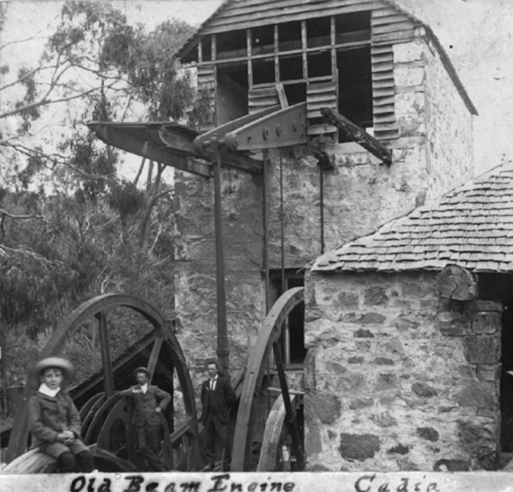
This is the earliest surviving photograph of the Cadia Engine House, predating the scrapping of the engine around 1916. The Crusher House is on the right, and the lean-to roof of the Boiler House is on the left, with the end wall left open for ventilation.
History.
The Cadia or White Engine House was built on the South Section Mine at West Cadia in 1865. It was purchased in 1859 by the Scottish Australian Mining Company and was originally intended for the Goodhope Mine at Yass. It was stored in Sydney until transported to Cadia in 1862. There is evidence to suggest that the engine was being erected at East Cadia in 1862-1863 before work was stopped. With the formation of the Cadiangullong Consolidated Copper Mining Company in 1864, the construction of the engine at West Cadia could proceed with certainty and was completed in 1865. The life of the engine was relatively short, working continuously until the mine closed in 1868, although it was worked sporadically thereafter. The engine was removed for scrap around 1916.
Manufacture.
The engine was manufactured at the Charlestown Foundry, established in 1827 by well-known engineers, J. and R. Michell, near Charleston Harbour, St. Austell, Cornwall. The Foundry was purchased by John Thomas in 1835 and he was joined in the business by his sons, Edwin and James, in 1854. John Thomas & Company built the engine for the Scottish Australian Mining Company in 1859.
John Thomas sold the Charlestown Foundry in 1866. The foundry, though one of the smaller examples in Cornwall, is famous for manufacturing the last Cornish pumping engine in 1911.
Description.
Although the main elements of the Cadia or White Engine House survive in good condition, to the lay person it is still difficult to comprehend how it worked.
The main buildings are all built of stone, crafted in the solid Cornish manner, except for the top of the chimney, which is of attractive red coloured sandstock brick. The engine house is the central element, originally with its beam engine, which drove two flywheels. Hence it is known as a rotative beam engine with the following specifications. The cylinder was 25 inches in diameter, with a 9 feet piston stroke, and was rated at 50 hp. The main beam is calculated to have been 16 feet 3 or 4 inches in length. It was attached to two 20 foot diameter flywheels.
The boiler house, now in a very ruinous state due to the removal of the 10 ton Cornish boiler, is located on the west side of the engine house and the chimney is detached and slightly to the north. The boiler, of which three parts survive, was larger than normal. It measured 31 feet long, 7 feet in diameter and had a 4 feet diameter flue. Each strake or ring of 5 plates is joined telescopically to the next, an unusual design.
The engine performed a number of essential tasks. It is located approximately 140 feet (42.5 metres) north of Phillip’s Shaft. Through a winding drum attached to one of the flywheels and connecting to headgear over the shaft, it raised ore from this shaft. The engine flywheel was also connected through a series of flat rods to a 7 inch Cornish pump in Phillip’s Shaft. To counterbalance the weight of the pitwork associated with this pump, there would have been a balance bob at the top of the shaft.
The water pumped up from the mine would have been used in the boiler and for ore processing. The primitive system of buddles or jigging plant is described by the Wandering Reporter in the Sydney Mail of 1865. The buddles were located on the upper ore processing floor to the south of the engine house, together with a stone breaker, this equipment also being driven by the engine.
The copper ores were fed through the Cornish crusher rolls, housed in the Crusher House and driven by the engine. This building was located at right angles to the engine house on its east side and directly in line with the flywheels of the engine. Once the ore was sorted and crushed to the required grade, it was taken out onto the lower ore processing floor on the north and east side of the engine house and carted down the hill to Smelter No. 1.
One of the essential elements of the engine was the brake attached to the flywheel. The remains of the wooden brake shoe are still located on site. The engine had to stop and start, especially when raising ore. It also worked in reverse to lower the ore bucket or kibble back down the shaft. The sale notice of 1868 also suggests the engine drove sawing machinery, but nothing of the latter survives.
The engine house is only part of the workings on the South Section Mine and its neighbour the North Section Mine at West Cadia. The remains are characterised by shafts, adits and mullock heaps. Their original extent can be seen in a series of plans, dated to 1878 and 1881. The surviving mining landscape provides an authentic and well preserved setting for the engine house.
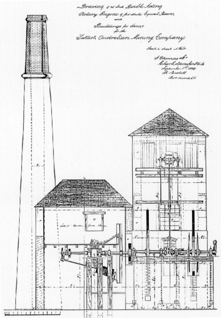
This is a copy of an original plan of the Cadia Engine, prepared by the manufacturers, J. Thomas & Company, Charlestown Foundry, Cornwall. It shows the planned layout of the engine and buildings, but when constructed the Crusher House was placed on the opposite side of the engine house. No boiler house is shown and the chimney is also in a different location (Margaret Morris).
-
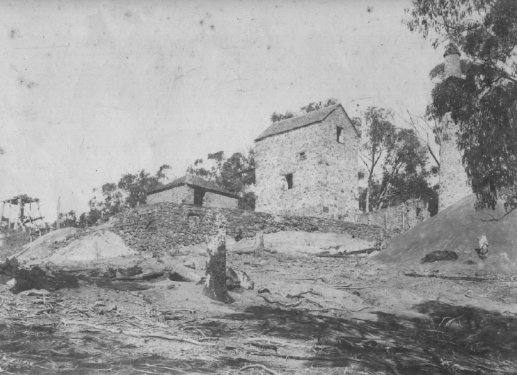
In this photograph the engine bob is still in place, but the Boiler House has lost its roof, with the walls supported by a number of ties. On the left is the headframe for Phillip’s Shaft (French Collection).
-
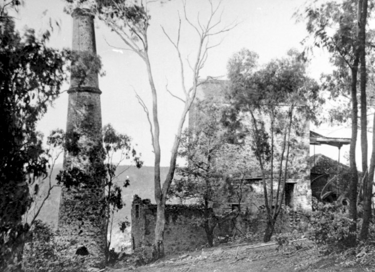
Seen from the west side, this photograph more clearly shows the unroofed state of the boiler house, while the engine bob is still in place (Margaret Morris).